X-keys Matrix Encoder Board Data Report | Main Page
General Information
|
VID
|
05f3h
|
|---|---|
|
PID #1 (Factory Default)
|
0406h or 1030
|
|
PID #2
|
0407h or 1031
|
|
PID #3
|
0408h or 1032
|
|
PID #4*
|
04E7h or 1255
|
|
Consumer Usage Page
|
1
|
|
Usage Page
|
000Ch or 12
|
*Available only on firmware version 18 or higher.
PID #1 Endpoints: Consumer Usage Page Input and Output (Hid Usage Page 12,
Hid Usage 1), Mouse (Hid Usage Page 1, Hid Usage 2), Keyboard (Hid Usage
Page 1, Hid Usage 6).
PID #2 Endpoints: Consumer Usage Page Output (Hid Usage Page 12, Hid Usage
1), Mouse (Hid Usage Page 1, Hid Usage 2), Keyboard (Hid Usage Page 1, Hid
Usage 6) and Joystick (Hid Usage Page 1, Hid Usage 4). The use of this PID
is mainly for Hardware Mode. Hardware Mode allows users to store macros
to the device itself using the MacroWorks
3.1 programming utility. Once the macros are stored they will work on
any computer or OS that supports HID.
PID #3 Endpoints: Consumer Usage Page Input and Output (Hid Usage Page 12,
Hid Usage 1), Joystick (Hid Usage Page 1, Hid Usage 4), Keyboard (Hid Usage
Page 1, Hid Usage 6).
PID #4 Endpoints: Consumer Usage Page Output (Hid Usage Page 12, Hid Usage
1), Mouse (Hid Usage Page 1, Hid Usage 2), Keyboard (Hid Usage Page 1, Hid
Usage 6) and Multimedia (Hid Usage Page 12 and 1, Hid Usage 1 and 128).
The use of this PID is mainly for Hardware Mode. Hardware Mode allows users
to store macros to the device itself using the MacroWorks
3.1 programming utility. Once the macros are stored they will work on
any computer or OS that supports HID. This endpoint is available only to
units with firmware version of 18 or higher.
X-keys Matrix Encoder Board is supported by P.I. Engineering Macroworks 3.1, X-keys Basic Setup for PC users, our P.I. Engineering SDK for Microsoft C# .NET, VB .NET, C++, our Linux SDK, and our Mac OS X SDK.
X-keys Matrix Encoder Board Input Report
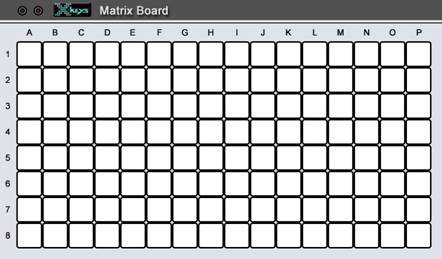
Figure 1: X-keys Matrix Encoder Board key reference.
Report Length: 33 bytes.
1. General Incoming Data
This data is returned when new data is detected such as button presses, unit id change. This report can be manually stimulated by sending a Generate Data output report which is very useful for obtaining the initial state of the device immediately after enumeration. This report is available only in PID #1 and PID #3.
|
Byte 1*
|
Byte 2
|
Byte 3
|
Byte 4
|
Byte 5
|
Byte 6
|
Byte 7
|
Byte 8
|
Byte 9
|
Byte 10
|
Byte 11
|
Byte 12
|
Byte 13
|
Byte 14
|
Byte 15
|
Byte 16
|
Byte 17
|
Byte 18
|
Byte 19
|
Bytes 20-23
|
Bytes 24-33
|
| Constant | Unit ID | Data Type | Keys A | Keys B | Keys C | Keys D | Keys E | Keys F | Keys G | Keys H | Keys I | Keys J | Keys K | Keys L | Keys M | Keys N | Keys O | Keys P | Time Stamp | Reserved |
|
0
|
<data>
|
PS
|
DI
|
DI
|
DI
|
DI
|
DI
|
DI
|
DI
|
DI
|
DI
|
DI
|
DI
|
DI
|
DI
|
DI
|
DI
|
DI
|
Time
|
value
|
PS: 0 if program switch unset, 1 if program switch is set, 2 if
generated by the Generate Data (output report 6) and program switch is unset,
3 if generated by the Generate Data (output report 6) and program switch
is set.
DI: For all bits 0 if key is up, 1 if key is down. Bits 1 to 8 correspond
to rows 1-8 respectively of the given column. For example Byte 4 gives the
state of A1, A2, A3, A4, A5, A6, A7 and A8. A value of 67 in this byte would
indicate that A1, A2 and A7 are pressed.
Time: If enabled using Enable Time Stamp output report gives a time
in ms from start of computer in 4 bytes where byte 20 is the MSB and byte
23 is the LSB.
2. Descriptor Data
This data is returned after a Request for Descriptor output report is sent. This report is available only in PID #1 and PID #3.
|
Byte 1*
|
Byte 2
|
Byte 3
|
Byte 4
|
Byte 5
|
Byte 6
|
Byte 7
|
Byte 8
|
Byte 9
|
Byte 10
|
Byte 11
|
Byte 12
|
Byte 13
|
Byte 14
|
Bytes 15-33
|
| Constant | Unit ID | Data Type | Mode | Key mapstart | Layer2 Offset | Write Report Length-1 | Read Report Length-1 | Max Columns | Max Rows | LED State | Version | PID Low | PID Hi | Reserved |
|
0
|
<data>
|
214
|
Mode
|
32
|
130
|
35
|
32
|
16
|
8
|
LEDs
|
<data>
|
PIDL
|
PIDH
|
value
|
Mode: 0 means device is in PID #1, 2 means the device is in PID
#2.
LEDs: bit 7=1 for Green LED on, 0 for Green LED off, bit 8=1 for
Red LED on, bit 8=0 for Red LED off.
PIDL: The LSB of the Product Identification number or PID.
PIDH: The MSB of the Product Identification number or PID.
3. Custom Data, available only on firmware version 18 or higher.
This data is returned after an output report: Generate Custom Data is sent. This report is available only in PID #1 and PID #3.
|
Byte 1*
|
Byte 2
|
Byte 3
|
Byte 4
|
Byte 5
|
Byte 6
|
Byte 7
|
Bytes Count+5 to 36
|
Byte 37
|
| Constant | Unit ID | Data Type | Count of custom bytes to follow | Custom byte 1 | Custom byte 2 | Custom byte 3... | Reserved | Increment |
|
0
|
<data>
|
224
|
Count
|
B1
|
B2
|
B3...
|
value
|
Increment
|
Count: Number of custom bytes to follow.
B1: 1st custom byte.
B2: 2nd custom byte.
B3: 3rd custom byte and so on for as many bytes as specified in Count.
Increment: This byte is incremented each time a Custom Data report
is sent thus even if 2 identical reports are sent they will both come in
even if SuppressDuplicate reports is on.
4. Check Dongle Key
This is received immediately following a Check Dongle Key output report is sent. The four values R0-R3 are required to continue the check. See Dongle Implementation for further details.
|
Byte 1*
|
Byte 2
|
Byte 3
|
Byte 4
|
Byte 5
|
Byte 6
|
Byte 7
|
Bytes 8 to 36
|
| Constant | Unit ID | Data Type | 1st byte returned from hash | 2nd byte returned from hash | 3rd byte returned from hash | 4th byte returned from hash | Reserved |
|
0
|
<data>
|
193
|
R0
|
R1
|
R2
|
R3
|
value
|
R0: Value need for comparison to check for correct dongle key.
R1: Value need for comparison to check for correct dongle key.
R2: Value need for comparison to check for correct dongle key.
R3: Value need for comparison to check for correct dongle key.
X-keys Matrix Encoder Board Output Report
The following types of output reports are shown in the summary below. Please be aware that several of these commands result in writing to the device's eeprom which has a limit to the number of writes allowed before it is "burnt out". The manufacturer's specification is 50,000 eeprom writes. Because of this we recommend the commands designated with e be executed rarely and not within timing loops. Note, the first byte listed in this documentation is 0 and represents the report ID. This is not present on some non-PC operating systems. So when sending an output report on Android for example, eliminate this byte.
|
Report
|
Format
|
Description
|
|---|---|---|
|
1
|
0, 186, LEDs, 0... | Set LEDs |
|
2
|
0, 179, LEDIndex, State, 0... | Index Based Set LED (Flash) |
|
3
|
0, 189, UnitID, 0... | Set Unit IDe |
|
4
|
0, 214, 0... | Request Descriptor |
|
5
|
0, 210, Enable, 0... | Enable Time Stamp |
|
6
|
0, 177, 0... | Generate Data |
|
7
|
0, 180, Freq, 0... | Set Frequency of Flash |
|
8
|
0, 204, Mode, 0... | Change PIDe |
|
9
|
0, 215, Mode, 0... | External Diodese |
|
10
|
0, 201, Modifier, 0, HC1, HC2, HC3, HC4, HC5, HC6, 0... | Keyboard Reflector |
|
11
|
0, 203, Buttons, Mouse X, Mouse Y, Wheel X, Wheel Y, 0... | Mouse Reflector (PID #1, PID #2, PID #4 only) |
|
12
|
0, 202, Joystick X, Joystick Y, Joystick Z rot., Joystick Z, Joystick Slider, Game Buttons 1, Game Buttons 2, Game Buttons 3, Game Buttons 4, 0, Point of View Hat, 0... | Joystick Reflector (PID #2 and PID #3 only) |
|
13
|
0, 224, Count, B1, B2, B3..., 0... | Generate Custom Data* |
|
14
|
0, 225, Usage ID LSB, Usage ID MSB, 0... | Multimedia Reflector (PID #4 only)* |
|
15
|
0, 195, Version LSB, Version MSB, 0... | Set Version Numbere* |
|
16
|
0, 238, 0... | Reboot Device |
|
17
|
0, 192, K0, K1, K2, K3, 0... | Set Dongle Keye |
|
18
|
0, 193, N0, N1, N2, N3, 0... | Check Dongle Key |
eCommand writes to EEPROM, do not
perform this command excessively, do not exceed 50,000 writes to EEPROM.
*Available only on firmware version 18 or higher.
Endpoint: 4, Vendor Defined Usage Page.
Report Length: 36 bytes.
1. Set LEDs
One of two methods for controlling the LEDs.
|
Byte 1*
|
Byte 2
|
Byte 3
|
Bytes 4-36
|
| Constant | Command | LED Control | Constant |
|
0
|
186
|
LEDs
|
0
|
LEDs: Bits 1-6=0,bit 7=1 to turn on Green LED or 0 to turn off Green LED, bit 8=1 to turn on Red LED or 0 to turn off Red LED.
2. Index Based Set LED (Flash)
One of two methods for controlling the LEDs. If flashing of LEDs is desired this method must be used.
|
Byte 1*
|
Byte 2
|
Byte 3
|
Byte 4
|
Bytes 5-36
|
| Constant | Command | LED Index | LED State | Constant |
|
0
|
179
|
LEDIndex
|
LEDState
|
0
|
LEDIndex: 6 = green, 7 = red.
LEDState: 0 = off, 1 = on and 2 = flash. Set the frequency of the
flash with output report Set Frequency of Flash.
3. Set Unit ID
Send this output report to set the Unit ID of the device. This is useful if connecting more than one of the same device to the a computer. Command writes to EEPROM, do not perform this command excessively, do not exceed 50,000 writes to EEPROM.
|
Byte 1*
|
Byte 2
|
Byte 3
|
Bytes 4-36
|
| Constant | Command | Unit ID (0-255) | Constant |
|
0
|
189
|
value
|
0
|
4. Request Descriptor
After sending this output report a Descriptor input report will be generated. Note input reports are available in PID #1 and PID #3 only.
|
Byte 1*
|
Byte 2
|
Bytes 3-36
|
| Constant | Descriptor Command | Constant |
|
0
|
214
|
0
|
5. Enable Time Stamp
By default the Time Stamp feature is enabled. To turn off send this command with Byte 3=0.
|
Byte 1*
|
Byte 2
|
Byte 3
|
Bytes 4-36
|
| Constant | Command | Enable | Constant |
|
0
|
210
|
0=off, 1=on
|
0
|
6. Generate Data
After sending this output report a General Incoming Data input report will be generated with bit 2 of PS set. This is useful in determining the initial state of the device before any data has changed. Note input reports are available in PID #1 and PID #3 only.
|
Byte 1*
|
Byte 2
|
Bytes 3-36
|
| Constant | Command | Constant |
|
0
|
177
|
0
|
7. Set Frequency of Flash
Use this output report to control the frequency of the flashing of the indicator LEDs.
|
Byte 1*
|
Byte 2
|
Byte 3
|
Bytes 4-36
|
| Constant | Command | Frequency | Constant |
|
0
|
180
|
Freq
|
0
|
Freq: 1-255 where 1 is the fastest flash and 255 is the slowest. 255 is approximately 4 seconds between flashes.
8. Change PID
Send this output report to change between the PIDs. Command writes to EEPROM, do not perform this command excessively, do not exceed 50,000 writes to EEPROM.
|
Byte 1*
|
Byte 2
|
Byte 3
|
Bytes 4-36
|
| Constant | Command | Mode | Constant |
|
0
|
204
|
Mode
|
0
|
Mode: 0 for PID #1, reporting to the USB as a Splat device (IN and OUT), mouse, keyboard. 1 for PID #2, reporting as a Splat device (OUT), mouse, joystick, keyboard. 2 for PID #3, reporting as a Splat device (IN and OUT), joystick, keyboard. 3 for PID #4, reporting as a Splat device (OUT), mouse, multimedia, keyboard. IMPORTANT do not enter any values other than 0, 1, 2, or 3 with this command.
9. External Diodes
Send this output report with Mode=0 if the matrix board has external diodes connected to the key matrix. Send this output report with Mode=1 if no external diodes are connected to the key matrix. Factory default is Mode=0, with external diodes. This command needs to be sent only once and the setting is saved in the eeprom. Command writes to EEPROM, do not perform this command excessively, do not exceed 50,000 writes to EEPROM.
|
Byte 1*
|
Byte 2
|
Byte 3
|
Bytes 4-36
|
| Constant | Command | Mode | Constant |
|
0
|
215
|
Mode
|
0
|
Mode: 0 if external diodes are present, 1 if external diodes are not present.
10. Keyboard Reflector
Sends native keyboard messages.
|
Byte 1*
|
Byte 2
|
Byte 3
|
Byte 4
|
Byte 5
|
Byte 6
|
Byte 7
|
Byte 8
|
Byte 9
|
Byte 10
|
Bytes 11-36
|
| Constant | Command | Modifier | Constant | Hid Code 1 | Hid Code 2 | Hid Code 3 | Hid Code 4 | Hid Code 5 | Hid Code 6 | Constant |
|
0
|
201
|
Modifier
|
0
|
HC1
|
HC2
|
HC3
|
HC4
|
HC5
|
HC6
|
0
|
Modifier: Bit 1=Left Ctrl, bit 2=Left Shift, bit 3=Left Alt, bit
4=Left Gui, bit 5=Right Ctrl, bit 6=Right Shift, bit 7=Right Alt, bit 8=Right
Gui.
HC1=Hid Code for 1st key down, or 0 to release previous key press
in this byte position.
HC2=Hid Code for 2nd key down, or 0 to release previous key press
in this byte position.
HC3=Hid Code for 3rd key down, or 0 to release previous key press
in this byte position.
HC4=Hid Code for 4th key down, or 0 to release previous key press
in this byte position.
HC5=Hid Code for 5th key down, or 0 to release previous key press
in this byte position.
HC6=Hid Code for 6th key down, or 0 to release previous key press
in this byte position.
11. Mouse Reflector
Sends native mouse messages. Available only to PIDs with mouse endpoint; PID #1, PID #2 and PID #4.
|
Byte 1*
|
Byte 2
|
Byte 3
|
Byte 4
|
Byte 5
|
Byte 6
|
Byte 7
|
Bytes 8-36
|
| Constant | Command | Buttons | Mouse X | Mouse Y | Wheel X | Wheel Y | Constant |
|
0
|
203
|
Buttons
|
X
|
Y
|
WX
|
WY
|
0
|
Buttons: Bit 1=Left, bit 2=Right, bit 3=Center, bit 4=XButton1,
bit 5=XButton2.
X=Mouse X motion. 0 no motion, 1-127 is right, 255-129=left,
finest inc (1 and 255) to coarsest (127 and 129).
Y=Mouse Y motion. 0 no motion, 1-127 is down, 255-129=up, finest
inc (1 and 255) to coarsest (127 and 129).
WX=Wheel X. 0 no motion, 1-127 is up, 255-129=down, finest inc
(1 and 255) to coarsest (127 and 129).
WY=Wheel Y. 0 no motion, 1-127 is up, 255-129=down, finest inc
(1 and 255) to coarsest (127 and 129).
12. Joystick Reflector
Sends native joystick messages. Available to PIDs with Joystick endpoint; PID #2, PID #3.
|
Byte 1*
|
Byte 2
|
Byte 3
|
Byte 4
|
Byte 5
|
Byte 6
|
Byte 7
|
Byte 8
|
Byte 9
|
Byte 10
|
Byte 11
|
Byte 12
|
Byte 13
|
Bytes 14-36
|
| Constant | Command | Joystick X | Joystick Y | Joystick Z rot. | Joystick Z | Joystick Slider | Game Buttons | Game Buttons | Game Buttons | Game Buttons | Constant | Point of View Hat | Constant |
|
0
|
202
|
X
|
Y
|
Z rot.
|
Z
|
Slider
|
GB1
|
GB2
|
GB3
|
GB4
|
0
|
Hat
|
0
|
X: Joystick X, 0-127 is from center to full right, 255-128 is from
center to full left.
Y: Joystick Y, 0-127 is from center to bottom, 255-128 is from center
to top.
Z rot.: Joystick Z rot., 0-127 is from center to bottom, 255-128
is from center to top.
Z.: Joystick Z, 0-127 is from center to bottom, 255-128 is from center
to top.
Slider: Joystick Slider, 0-127 is from center to bottom, 255-128
is from center to top.
GB1: Game buttons 1-8, bit 1= game button 1, bit 2=game button 2,
etc.
GB2: Game buttons 9-16, bit 1= game button 9, bit 2=game button 10,
etc.
GB3: Game buttons 17-24, bit 1= game button 17, bit 2=game button
18, etc.
GB4: Game buttons 25-32, bit 1= game button 25, bit 2=game button
26, etc.
Hat: 0 to 7 clockwise, 8 is no hat.
13. Generate Custom Data, available only on firmware version 18 or higher.
After sending this output report a Custom Data input report will be generated with Byte 3 set to 224 and the count and custom bytes following. Note input reports are available in PID #1 and PID #3 only.
|
Byte 1*
|
Byte 2
|
Byte 3
|
Byte 4
|
Byte 5
|
Byte 6...
|
Bytes (Count+4) to 36
|
| Constant | Command | Count of custom bytes to follow | Custom byte 1 | Custom byte 2 | Custom byte 3... | Constant |
|
0
|
224
|
Count
|
B1
|
B2
|
B3...
|
0
|
Count: Number of custom bytes to follow.
B1: 1st custom byte.
B2: 2nd custom byte.
B3: 3rd custom byte and so on for as many bytes as specified in Count.
14. Multimedia Reflector, available only on firmware version 18 or higher.
Sends 2 byte multimedia messages. Must have the device set to a PID with a multimedia endpoint; PID #4. When in this PID there is no input data report available thus users of this feature will not be able to read any data, only write output reports. If desiring this feature users are instructed to use MacroWorks 3.1 programming utility for programming of the buttons and converting to a multimedia PID. This command must be followed with an "up" command with ULo and UHi =0.
|
Byte 1*
|
Byte 2
|
Byte 3
|
Byte 4
|
Bytes 8-36
|
| Constant | Command | Usage ID Lo | Usage ID Hi | Constant |
|
0
|
225
|
ULo
|
UHi
|
0
|
ULo=Usage ID low byte see hut1_12.pdf, pages 75-85 Consumer Page.
UHi=Usage ID high byte see hut1_12.pdf, pages 75-85 Consumer Page.
Example: My Computer - 0, 225, 94, 01, 0... and send report using WriteData. Then 0, 225, 0, 0, 0... and send report using WriteData. In this example 0194 is the Usage ID for My Computer.
15. Set Version Number, available only on firmware version 18 or higher.
Send this output report to set the Version of the device. This is not the firmware version given in the descriptor but a 2 byte number available on enumeration. The value is "remembered" so if it is changed, using this report, the device must be rebooted. The device can be rebooted by replugging it or by sending the output report : Reboot Device. The device is also rebooted when changing pids using output report: Change PID. Command writes to EEPROM, do not perform this command excessively, do not exceed 50,000 writes to EEPROM.
|
Byte 1*
|
Byte 2
|
Byte 3
|
Byte 4
|
Bytes 5-36
|
| Constant | Command | Version LB (0-255) | Version HB (0-255) | Constant |
|
0
|
195
|
value
|
value
|
0
|
16. Reboot Device
Send this output report to reboot the device without having to unplug it. After sending this report the device must be re-enumerated.
|
Byte 1*
|
Byte 2
|
Bytes 3-36
|
| Constant | Command | Constant |
|
0
|
238
|
0
|
17. Set Dongle Key
Sets the user entered key. Remember these numbers as they are required to check for the key. This is intented to be done once by the developer prior to sale. See Dongle Implemenation for more details. Command writes to EEPROM, do not perform this command excessively, do not exceed 50,000 writes to EEPROM.
|
Byte 1*
|
Byte 2
|
Byte 3
|
Byte 4
|
Byte 5
|
Byte 6
|
Bytes 7-36
|
| Constant | Command | 1st byte of key | 2nd byte of key | 3rd byte of key | 4th byte of key | Constant |
|
0
|
192
|
K0
|
K1
|
K2
|
K3
|
0
|
K0: 1st byte of user determined dongle key, any number 1-254.
K1: 2nd byte of user determined dongle key, any number 1-254.
K2: 3rd byte of user determined dongle key, any number 1-254.
K3: 4th byte of user determined dongle key, any number 1-254.
18. Check Dongle Key
Checks the key that was entered in Set Dongle Key. This is intented to be done by the developer within their own software to determine if the connected X-keys device is the one they sold to the customer. 4 random bytes along with the actual key are entered into the DongleCheck2() hash function of the Piehid32.dll/PieHid32Net.dll which returns 4 bytes. Then after sending this output report a Check Dongle Key input report will be received containing the same 4 bytes returned from the hash if the key matches. See Dongle Implemenation for more details.
|
Byte 1*
|
Byte 2
|
Byte 3
|
Byte 4
|
Byte 5
|
Byte 6
|
Bytes 7-36
|
| Constant | Command | Random number | Random number | Random number | Random number | Constant |
|
0
|
193
|
N0
|
N1
|
N2
|
N3
|
0
|
K0: 1st byte of a random number that was used in the hash, any number
1-254.
K1: 2nd byte of a random number that was used in the hash, any number
1-254.
K2: 3rd byte of a random number that was used in the hash, any number
1-254.
K3: 4th byte of a random number that was used in the hash, any number
1-254.
*This first byte may be omitted on some non-PC operating systems. On these systems the read and write lengths will be 1 byte smaller.
Back to top